What Your Robot's Payload Rating Doesn't Tell You
Rated payload is measured mid-reach. At full extension it can drop 20-40 percent, and wrist inertia is the spec that actually bites.
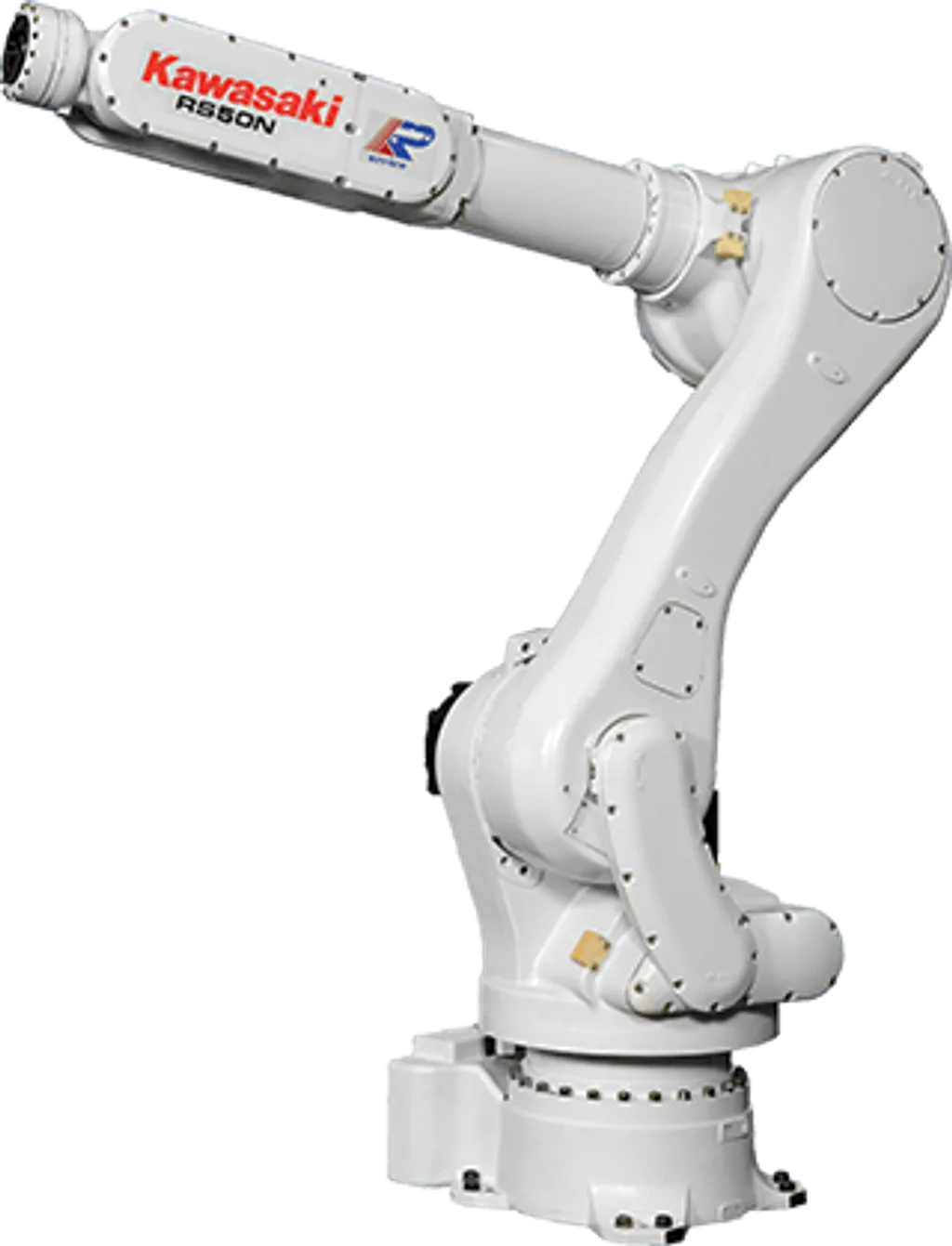
The number on the datasheet is not the number you can use. A robot rated at 10 kg payload will typically handle only 6-8 kg at full reach extension, and if your gripper has any mass offset from the flange, you may trigger servo faults before a single part ever touches the tool. Payload rating is a marketing number measured at the robot’s comfortable mid-reach sweet spot, roughly 60-75% of maximum arm extension. Nobody prints the number you actually need for the job.
Where Is Rated Payload Actually Measured?
Every major robot vendor specifies payload at a standardized test condition: arm at roughly 60-75% of maximum reach, wrist in a nominal orientation, moving at a moderate cycle speed. That is the condition where the robot’s servo system and structural deflection are at their most favorable.
Move the arm out to full extension and the picture changes. The moment arm on each joint increases, the torque demand on the wrist and elbow joints rises, and the servo drive’s rated torque capacity has less headroom. The result is a payload capacity that drops approximately 20-40% relative to the rated figure, depending on arm geometry and reach.
A worked example using a mid-range 10 kg articulated arm with 1.5 m reach:
| Condition | Effective Payload | Notes |
|---|---|---|
| 60% reach (rated condition) | 10.0 kg | Published spec |
| 80% reach | 8.2 kg | ~18% reduction |
| Full reach (1.5 m) | 6.5 kg | ~35% reduction |
| Full reach + 5 kg gripper | 1.5 kg | Net capacity for part |
The bottom row is where projects die. At full reach with a real gripper attached, a “10 kg” robot might carry 1.5 kg of actual part. If your part weighs 3 kg, you are shopping for a 20 kg robot, not a 10 kg one.
Industrial Robotics Hub now publishes a “payload at full reach” figure on robot detail pages wherever the manufacturer or integrator community has verified it. Browse the full articulated robot catalog to compare robots with that figure included.
How Much Does Your Gripper Actually Weigh?
Before a single part reaches the robot’s fingers, you have already spent payload budget on the end-of-arm tooling (EOAT). A typical pneumatic gripper for light assembly runs 2-3 kg. Add a quick-change adapter (0.4-0.8 kg), a force-torque sensor (0.3-0.6 kg), and a vision camera (0.3-0.5 kg), and the EOAT stack reaches 5-8 kg without trying.
On a robot rated at 10 kg, that leaves 2-5 kg for the part at rated conditions. At full reach, with the 35% capacity reduction applied, you may have under 2 kg of usable net payload. This is why integrators routinely size up one class when tooling complexity is unknown at quotation time.
The robot comparison tool at Industrial Robotics Hub lets you filter by rated payload and add a tooling offset to see net capacity side by side. Use it before you spec.
What Is Wrist Inertia and Why Does It Bite?
This is the spec that causes the most unexpected field problems, and it appears in the footnotes of most datasheets rather than the headline.
Rated payload assumes the load is positioned at a specific center of gravity distance from the flange, typically 0 mm or a small standard offset. The moment of inertia (J) of the load about the wrist axes scales with the square of the distance: J = m × r². A 5 kg part centered 0.05 m off the flange produces roughly 0.013 kg·m² of inertia about the wrist. Move that same 5 kg to 0.3 m off the flange and inertia rises to 0.45 kg·m², about 35 times higher.
Consider the FANUC LR Mate 200iD/7L, a 7 kg payload arm used widely in light assembly and inspection. Its maximum allowable wrist axis (J6) inertia is typically around 0.145 kg·m². A 5 kg gripper with its center of gravity 0.05 m from the flange sits at roughly 10-15% of that limit. The same gripper with a bracket that shifts the CG 0.3 m out exceeds the limit by more than 3x. The robot does not refuse to move. It will run, lose path accuracy at speed, and eventually generate servo alarms or overload faults that operators treat as random errors until someone measures the tooling.
Robotiq’s engineering team has documented this pattern: failing to set correct payload and inertia parameters degrades path accuracy and accelerates drive wear. The fix is to enter accurate tool mass, CG position, and inertia tensor in the robot controller. Most integrators skip this step on initial commissioning because it requires tooling drawings, not just a scale.
Wrist inertia: 5 kg load at varying CG offset (FANUC LR Mate 200iD/7L example, J6 max ~0.145 kg·m²)
J = m × r². Both 0.20 m and 0.30 m offset bars are capped at 100% display width; actual values exceed the axis limit.
What Does TCP Speed Spec Actually Mean?
Most robot datasheets list axis speed in degrees per second, not Cartesian millimeters per second. The TCP (tool center point) speed you actually get in mm/s depends on which joint is moving, the current arm configuration, and how far the TCP is from the rotating axis.
When a vendor lists “5,000 mm/s maximum TCP speed,” that number is achieved only in specific straight-line motions with optimal arm geometry. In a real pick-and-place cycle with approach, grasp, retract, and place motions, you are running a blend of joint moves. The average Cartesian TCP speed on a tight 400 mm pick-and-place arc is typically 30-60% of the headline figure.
This matters for cycle time calculations. If you size a robot based on “max TCP speed” divided by move distance, your predicted cycle time will be optimistic by a factor of 2 or more. Use vendor simulation software (FANUC ROBOGUIDE, ABB RobotStudio, KUKA.Sim) with your actual cell geometry before committing to a robot model.
The Planning Exercise: 10 kg at 1.5 m Reach
Here is how the budget works out for a real selection scenario. You need to pick a 10 kg steel casting from a conveyor at the robot’s maximum reach of 1.5 m and place it into a fixture 0.8 m away.
Step 1 - Establish tooling weight. A robust gripper for 10 kg steel: 3.5 kg fingers and body, 0.6 kg quick-change, 0.4 kg cabling and pneumatic fittings. EOAT total: 4.5 kg.
Step 2 - Establish required payload at point of pick. Part (10 kg) + EOAT (4.5 kg) = 14.5 kg at 1.5 m reach.
Step 3 - Work backward to rated spec. At full reach, capacity is roughly 65% of rated. Required rated capacity: 14.5 / 0.65 = 22.3 kg minimum.
Step 4 - Add inertia check. Gripper CG at 0.18 m from flange with the part gripped. Check J = (14.5) × (0.18²) = 0.47 kg·m². Verify against the wrist inertia spec of your candidate robot. A 20 kg class robot typically allows 1.0-1.5 kg·m² at J6, so this passes. A smaller 15 kg robot might be marginal.
The robot you actually need for a “10 kg” application at full reach is a 20-25 kg rated arm. Browse the full robot catalog filtered to 20-30 kg payload to see candidates with reach and wrist inertia specs listed.
AMD Machines publishes a useful breakdown of how payload and reach interact across robot classes, including the distinction between dynamic payload (at speed) and static payload (at rest), which is another dimension most datasheets conflate.
Which Specs Should You Actually Check?
Before signing a purchase order, verify these five numbers, not just rated payload:
- Payload at full reach - Ask the vendor or integrator directly. IRH now publishes this for robots where it is documented.
- Maximum wrist moment (Nm) per axis - J4, J5, J6 independently. Your EOAT load case must clear all three.
- Maximum wrist inertia (kg·m²) per axis - Run J = m × r² for your gripper CG and compare.
- Payload curve or diagram - Some vendors publish a payload-vs-reach graph in the full technical manual (not the marketing datasheet). Find the manual.
- Dynamic vs static payload - A few vendors publish both. Static payload (arm not moving) is always higher. Your cycle is dynamic.
The robot comparison pages on Industrial Robotics Hub include wrist moment and inertia specs wherever the manufacturer publishes them, so you can compare candidates side by side without digging through six separate technical manuals.
The Honest Number
Payload rating is the number that fits on a product card. It is measured under favorable conditions by the people selling the robot. That does not make it dishonest, exactly - it is an industry-standard test condition. It just does not answer the question you need answered on a real cell: what can this robot actually carry, at the reach I need, with the gripper I have, without losing path accuracy at production speed?
The answer to that question is always smaller than the number on the datasheet, often by 40-50% when you account for reach and tooling combined. Size up. Verify inertia. And get the payload curve from the technical manual, not the marketing brochure.