Robot Cell Safety Clearance: Reach Envelope, Fence Height & ISO 13857
Robot cell clearance follows arm reach plus ISO 13857 safety distances. The 4,200 mm ABB IRB 8700 needs a guarded zone 4x wider than a 911 mm compact arm.
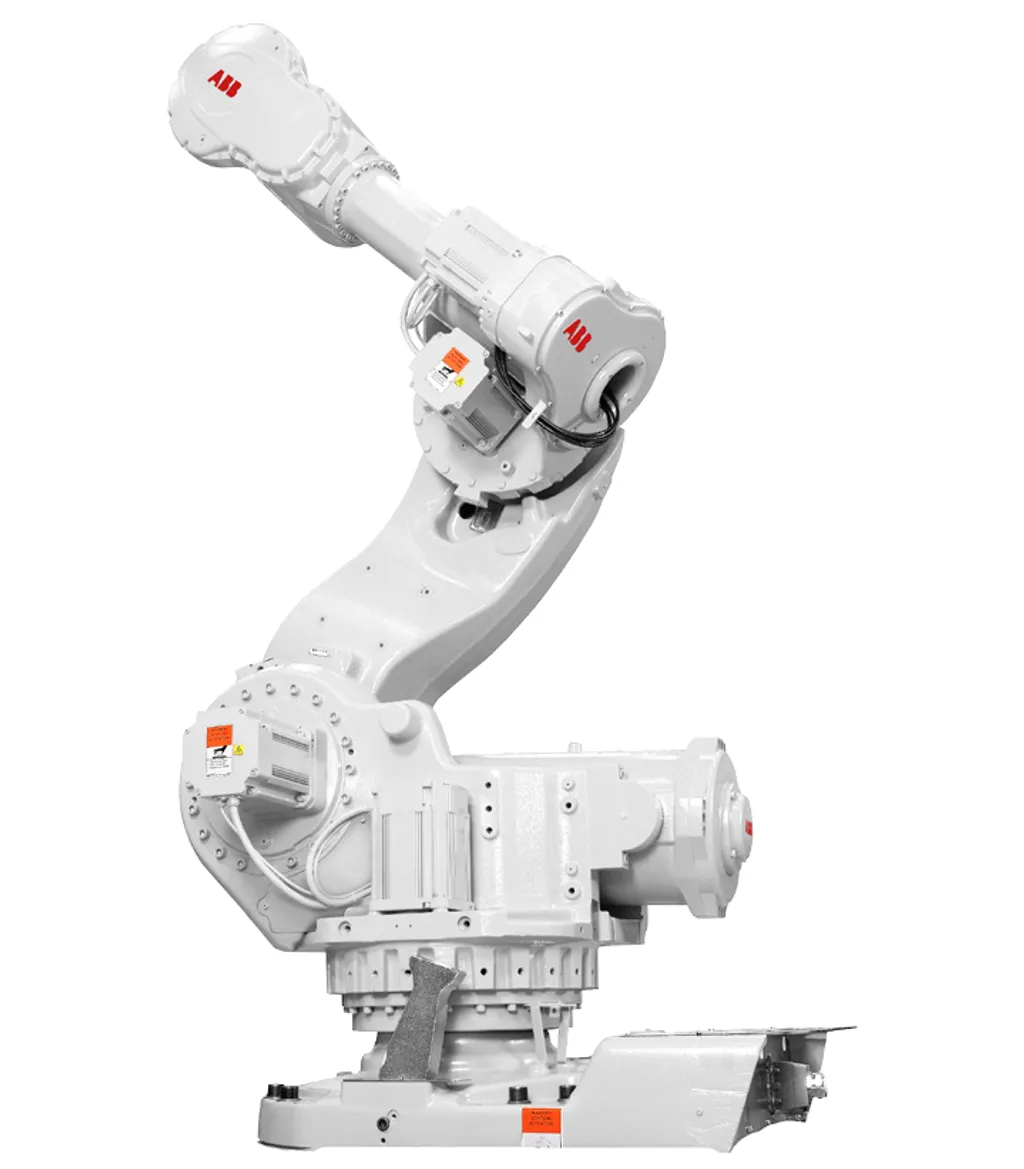
The guarded zone around a robot cell is not set by fencing convention or budget — it is driven by the arm’s swept envelope at full reach extension, plus the tooling that extends that envelope beyond the flange, plus the distance the arm travels after an emergency stop before it actually halts, plus the clearance a technician needs to work safely in the access aisle. Get any one of those four addends wrong and either you have an undersized cell that puts people inside the hazard zone, or you have a vastly overbuilt cell that wastes floor space and increases material handling costs.
A concrete starting point: an ABB IRB 7600 has a published reach of 2550 mm. Its theoretical guarded-zone diameter before any additional clearance or stopping distance is already over 5 metres. A FANUC LR Mate 200iD/7L at 911 mm reach needs roughly 1.8 metres. Those two robots might sit in the same factory, but they need fundamentally different layouts.
Why reach drives everything
The swept work envelope of an articulated arm approximates a sphere of radius equal to the maximum reach. In practice the envelope is not a perfect sphere — joint-limit geometry and counterbalance systems create voids at the base — but for conservative cell planning purposes, treating the envelope as a full sphere of radius R gives you a defensible worst case.
That sphere defines the minimum inner boundary of any guarded zone. Everything else adds to it:
Tool and part extension. The robot’s reach measurement ends at the tool-centre-point (TCP) or flange. A welding torch, gripper, or handling fixture adds length. A 200 mm torch on a 2550 mm arm raises the effective hazard radius to 2750 mm. Never plan a cell footprint using robot reach alone; plan it using reach plus the longest end-of-arm tool combination you will ever run in that cell.
Stopping distance after an e-stop or safety trip. A robot arm in motion does not halt instantly. The drive system brakes, but inertia carries the arm forward. Stopping distance depends on robot size, payload, speed, and the brake design. The standard path is to obtain the manufacturer’s stopping distance data and add it to the hazard radius. For large payloads at high speed, stopping distances of several hundred millimetres are realistic.
Human access clearance. ISO 13857 and the supporting robot integration standard ISO 10218-2:2025 require sufficient clearance between the hazard zone boundary and the physical guard that a person cannot be trapped between them. An access aisle of at least 500 mm — and often significantly wider for maintenance tasks — must be factored in.
The simplified planning formula looks like this: required cell radius from robot base = reach + tool extension + stopping distance + access clearance. The guarded-zone perimeter is then drawn at that radius, and the physical fence is located at or beyond the perimeter.
Our Factory Layout Planner computes this footprint from your arm’s reach and tool length, which is the fastest way to sanity-check a layout before committing to a floor plan.
Illustrative reach-to-zone geometry across our database
The table below shows five arms from our database with their published reach figures, the illustrative guarded-zone diameter that results from the 2x-reach approximation, and the relational context. The “illustrative guarded-zone diameter” column is purely geometric — it is 2 times the arm reach, representing the minimum space the swept envelope would occupy if centred in the zone. It does not include stopping distance, tool extension, or access clearance. It is labelled illustrative because it is not a compliance value; the actual cell layout must add all four addends described above.
| Robot | Reach (mm) | Illustrative guarded-zone diameter (mm) | Notes |
|---|---|---|---|
| FANUC LR Mate 200iD/7L | 911 | 1,822 | Compact workcell; smallest footprint in this sample |
| FANUC M-20iD/25 | 1,831 | 3,662 | Mid-range workhorse; most common category in our DB |
| ABB IRB 7600 | 2,550 | 5,100 | Heavy-payload cell; diameter exceeds 5 m before clearance |
| FANUC M-2000iA/1700L | 3,734 | 7,468 | Large-press tending and heavy assembly |
| ABB IRB 8700 | 4,200 | 8,400 | Longest-reach arm in our database |
Source: published reach figures from the Industrial Robotics Hub database. Illustrative guarded-zone diameter = 2 x reach. This is a planning geometry estimate, not a compliance calculation. Add stopping distance, tool extension, and access clearance to arrive at a real cell perimeter.
Across all 96 articulated arms in our database, reach spans 350 mm to 4200 mm with an average of approximately 1669 mm. That average arm implies an illustrative guarded-zone diameter of roughly 3.3 metres before any of the addends are applied. Choosing the wrong robot for a tight floor plan is a layout problem, not just a specification detail — it is worth running the geometry early.
For a side-by-side reach comparison between any two arms, the /compare/ tool lets you pull up any pair from the database.
Which standards govern clearance and guarding?
Three standards do most of the work, and they cover distinct scopes.
ISO 13857: Safety distances to prevent hazard zones being reached by upper and lower limbs. This is the primary reference for setting safe distances — specifically the physical gap between a hazard zone and any opening, aperture, or approach path in the guard structure. ISO 13857 contains tables that specify minimum distances based on the type of reach scenario: reaching over a guard, reaching through an opening, or reaching around a barrier. The exact millimetre values are in those tables and depend on the specific reach configuration; readers should consult the standard directly rather than relying on any summary. What the tables establish is a methodology: the guard height and the horizontal safety distance are interrelated, and meeting one without the other does not satisfy the standard. Fence and guard heights in perimeter safety applications are commonly seen in the rough range of 1400 mm to 2000 mm depending on the reach-over geometry and the distance from the hazard, but the exact value for any given installation comes from the ISO 13857 tables, not from a rule of thumb.
ISO 10218-2:2025: Robots and robotic devices — Safety requirements for robot systems and integration. This is the integrator’s primary standard for designing, building, and handing over a complete robot cell. It covers guarding selection, risk assessment methodology, safeguard verification, and the cell-level conformity process. The 2025 revision absorbed the collaborative-workspace requirements previously scattered across ISO/TS 15066. As covered in detail in our CE marking guide for robot cells, ISO 10218-2 is the standard that drives the integrator’s Declaration of Conformity — the cell-level document, not the arm manufacturer’s Declaration of Incorporation.
ISO/TS 15066 (superseded in ISO 10218-2:2025). Previously the reference for speed-and-separation monitoring and power-and-force limiting in collaborative applications. Still cited in older installations but now incorporated into ISO 10218-2:2025 for new work.
In the United States, OSHA references ANSI/A3 consensus standards (formerly ANSI/RIA) for industrial robot safety. The technical content aligns closely with the ISO framework, but US integrators should confirm applicable ANSI/A3 editions for domestic compliance.
Guarding types and how they interact with reach geometry
The reach envelope determines not just the zone size but which guarding approach is practical.
Fixed perimeter fencing is the baseline for most cells. A welded steel barrier at the calculated radius physically prevents human entry. It is simple, reliable, and the default starting point for any cell where continuous unattended operation is the primary mode. The ISO 13857 tables determine the required fence height relative to the horizontal distance from the hazard.
Interlocked gates are required wherever people need to enter the cell for part loading, maintenance, or tooling changes. The interlock must be performance-level rated per ISO 13849-1 and connected to a safety-rated monitored stop function. The gate geometry — and critically, the time delay between gate actuation and robot stop — must account for the arm’s stopping distance to ensure the robot has halted before the gate can be opened far enough for entry.
Light curtains and safety laser scanners (presence-sensing devices) are used where physical fencing would block material flow — conveyor entry points, pallet lanes, or where continuous manual loading makes gated access impractical. The safety distance between the sensing plane and the nearest hazard point must be calculated per ISO 13857 using the hand or whole-body reach coefficients, plus the system response time (sensor detection time plus robot stop time).
Speed-and-separation monitoring (SSM) and safety-rated monitored stop support hybrid cells where a robot and an operator share a workspace part of the time. SSM continuously adjusts robot speed based on the measured distance to the nearest human, reducing speed as the person approaches until a safety stop is triggered at the minimum separation distance. The geometry of these dynamic exclusion zones scales directly with the arm’s reach — a longer-reach arm covers more of the work area, which compresses the shared space and often demands more sophisticated sensing.
The cobot myth: “no fence needed”
A robot arm with a collaborative rating does not exempt the cell from guarding requirements. The ISO 10218-2:2025 framework — and the complementary risk assessment methodology — applies to every robot cell regardless of the arm’s collaborative classification.
The collaborative rating describes an operating mode, not a physical property. Power-and-force limiting mode limits contact force and pressure within defined thresholds. Those thresholds apply to the complete end-effector assembly including tooling and payload. A collaborative arm running at 250 mm/s with a sharp tool or a 10 kg part may exceed the contact-force limits regardless of what the arm’s nameplate says.
As the CE marking guide for robot cells describes, the risk assessment must be performed for the actual application. A genuine low-force, low-speed, light-payload collaborative task with an assessed and verified end-effector may allow a fence-free layout. The same arm running a different task at higher speed or with different tooling may require conventional guarding. The assessment drives the conclusion; the arm’s label does not.
Reach still matters even in collaborative cells. A larger-reach arm means a larger shared workspace, more potential for high-speed incursions in SSM mode, and greater inertia on an unexpected contact. The cell layout and risk assessment must address reach geometry even when the arm has collaborative hardware.
For a broader comparison of arm types and their specifications, the articulated robot category page lists all 96 articulated arms in our database with reach figures, payload, and collaborative classification.
How to size your cell: a working sequence
The factory layout question comes down to a repeatable sequence. Working through it in order avoids the common failure of designing the cell around an arm that does not fit the floor space, or discovering the guarding budget late.
1. Fix the reach requirement first. What is the longest reach the process actually demands — part size, fixture geometry, conveyor spacing, workpiece travel? Add tool length. That sum defines the minimum arm reach and, via the 2x geometry, the rough floor space the cell will consume. Use the Factory Layout Planner to translate reach into a footprint before selecting an arm.
2. Select the arm to match the reach, not the payload. Many integrators select by payload first and discover too late that the arm they chose does not have sufficient reach for the application. Reach and payload are independent parameters. A FANUC M-20iD/25 at 1831 mm reach and 25 kg payload covers a very different floor footprint than a FANUC M-2000iA/1700L at 3734 mm reach and 1700 kg payload — both are heavy-industrial arms but the cell layouts are incomparable. Review specifications for both on their robot pages before committing.
3. Obtain stopping distance data from the manufacturer. For the specific arm, payload configuration, and speed, ask the robot manufacturer for the worst-case stopping distance envelope. Add this to the hazard radius.
4. Apply ISO 13857 to set guard height and safety distances. With the hazard zone perimeter established, consult the ISO 13857 tables to determine the required guard height and the minimum horizontal safety distance between the guard and the hazard zone boundary. The tables account for the reach-over geometry; use them, not rules of thumb.
5. Choose guarding type to match the operational mode. Fixed fencing for unattended production, interlocked gates for access, light curtains for material flow lanes, SSM for shared-workspace tasks. Verify that the guarding performance level meets ISO 10218-2:2025 requirements.
6. Perform the full risk assessment under ISO 10218-2:2025. Size, guarding type, and stopping distance are inputs to the risk assessment, not outputs. The assessment must cover the full lifecycle — installation, normal operation, maintenance, and foreseeable misuse — and must result in a documented, signed record that supports the Declaration of Conformity.
The ABB IRB 7600 at 2550 mm reach is a useful calibration point: at the 2x illustrative geometry, the cell already needs over five metres of clear diameter before any safety distance is added. If your floor plan gives you four metres, the IRB 7600 is the wrong arm for that layout. Find that conflict in step one, not on commissioning day.
Standards bodies publish the authoritative documents: ISO 13857 at iso.org and ISO 10218-2:2025. For US-specific guidance, OSHA’s robot safety page references current ANSI/A3 editions. Consult an accredited safety engineer or notified body before finalising any cell design or conformity documentation.
Compare these robots